To begin with I made the mistake of going the easy way, I would not have had to search the internet a bit to reach the conclusion that a USB parallel converter does NOT work for our connection.
USB to Serial to Parallel Converter
This type of converters only speak about printer protocols (they also allow to incorporate scanners and in general hardware devices with parallel port), and so they let me know from the manufacturer directly when I contacted them trying to get some solution. The textual response was the following:
Unfortunatety that is not possible. This cable only supports the protocols for printers.
So nothing, I have it there in the closet.
Another commercial possibility is that discussed in pages such as Astrosnap, which refer to PCMCIA adapters to parallel port.
PCMCIA to parallel port converter
This option seems valid since I have seen comments that say so, however its price of approximately 60 Euros did not convince me too much, so I discarded it.
Now began the "odyssey", there was no choice but to seek and try to build it.
On the K3CCDTools page there is a famous scheme (many people refer to it) that could serve us perfectly, however, confused a bit because it talks about incorporporar a switch. It is also based on another scheme published on the page of Steve Chambers and that we can see here.
Diagram available on the K3CCDTools program page
What it seems is that its use is oriented to modifications that do not effect an automatic change between normal and long exposure mode and that change is made by actuating said switch. Therefore, in my case, I discarded this scheme as valid since the modification made with the integrated 4011 is totally automatic, so I kept searching ...
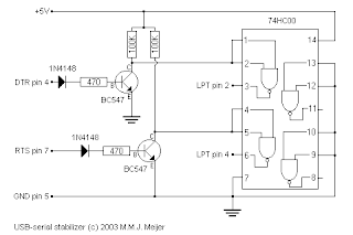
I found in some forums references to homemade constructions that incorporated the scheme facilitated by MMJ Meijer
Diagram available on the page of MMJ Meijer
making use of another integrated (a 74HC00) and definitely a construction more complicated than the previous scheme. Thinking logically, in theory the only thing that we need to be able to control the camera in normal or long exposure mode is a logical 1 or a logical 0, and that is really what is intended, so I was determined that the schemes could not be too complicated, it must be something very simple. I therefore discarded the scheme of MMJ Meijer, although I was about to try to implement it due to my continuous failures ... I have to say that I got in touch with him and he tried to help me, so from here my thanks.
Since patience is the mother of science, I kept looking for my simple scheme, something that was directly linked to my 4011 and allowed automatic control. Miraculously, I found a page of a person named Raphael MASSOT, with whom I was also chatting by e-mail about the problem and also tried to help me, so more thanks.
Diagram available on the page of R. Massot
Effectively this if it fits me, a very simple scheme and also, it referred to the use of the integrated 4011; I think I had found it. What is striking is that this type of scheme is very similar to the ones I have presented, in fact they are all based on the same thing but for the first time I had the conviction that this is the one that was going to work. And in fact, it is like that.
I built the circuit with the following components, recommended by Raphael Massot:
- Diode 1N4148
- Resistance 4K7Ohms
- Transistor BC547B
However, I had a difference that I thought was unimportant, and that is that the transistor that I had was a C547B and not a BC547B. Looking for the scheme of pinching and its possible equivalence, I did not find anything that would suggest that the one I had was not going to work. So I built the "invention" and, as you can imagine, it did not work even though I had to.
I continued looking for pages where someone had implemented this circuit, but I found nothing. At the end I left messages in several forums and I got in touch with a lot of people who did not know how to give me a correct answer, although they did not fail.
Finally, analyzing carefully and patiently the operation of the circuit and checking tensions, etc., (two or three hours researching), I came to the conclusion that what was not working was the transistor, the connection between collector and emitter (S1 and S2) did not start driving when a signal arrived at the base, through the resistance.
That's when I looked at my stock of transistors and found one that always worked for me in simple schemas, that is, a BC337. I put it on and I almost thought it was a lie that this was working.


No comments:
Post a Comment