Simple switch connection
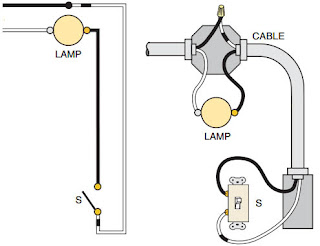
This is the most basic connection that can be found in an electrical installation. It consists of controlling a lamp from a single point. Here we have two types of schemes that represent the same circuit, the first is a functional scheme, it is clear and simple, and indicates the basic operation of the circuit. The second is a connection scheme, which although it has a pictorial form of the components, can also be presented in a symbolic form. This type of scheme represents the actual connection of the electrical components, as it would be in an installation.Basic Connections of Electrical Switches
 |
| Simple switch connection for the control of a lamp from one point (power supply per switch) |
The power supply may come from another circuit, or perhaps from the panel of circuit breakers or breakers. By pressing the "S" switch the "LAMP" lamp turns on, since the circuit was closed, and current can flow without problems. Note that the switch interrupts the black wire, this is the potential or live, and is the one that is always interrupted as a rule (NEC). The white wire is the neutral, and it is spliced into the switch box and carried to the lamp. Although you may think that you can carry the neutral cable directly, without having to connect it in the switch box, it is regulated that you must splice or screw the cables that reach each connection box, both the potential and the neutral itself. This facilitates the work for possible repairs or future derivations that are going to be carried out.
 |
| Simple switch connection for controlling a lamp from one point (lamp power supply) |
Three-way switch connection
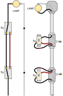
This is the most commonly used circuit for the connection of three-way switches. This circuit is used to control a lamp or group of lamps from two points, that is, switching on or off from two different locations. |
| Connection of the three-way switch for the control of a lamp from two points (power supply per switch) |
In this first state the lamp is on, since there is no interruption of the potential to the lamp. As soon as either of the two "S3" switches is operated, the lamp goes off. It is about switching the switches, until they are on the same common path to be able to let the current pass.
In the case of the connection circuit, the power supply enters through the switch box. The neutral (white wire) is connected to the first and second boxes, then goes to the lamp. The potential cable (black wire) is connected directly to the common switch "S3". From the other two screws, the traveling cables are removed (these conductors can be of the same color, of different colors, or identified with tape). Fixed, it is carried towards the traveling screws of the second switch, then the black wire is fixed in the common one, and it is connected directly to the lamp.
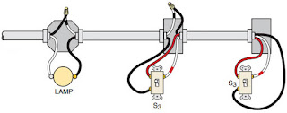
There are situations in which the connection may vary slightly. This is due to the way the circuit is powered, as well as the location where the lamp box or switches are located. In the following figures you can see those cases.
 |
| Connection of the three-way switch for the control of a lamp from two points (power supply per lamp). |
 |
| Connection of the three-way switch for the control of a lamp from two points (lamp power supply) |
Four-way switch connection
This circuit is not very usual to see it in an electrical installation. It works to control a lamp or group of lamps from three different points. This can also be used to control the lamps from more than three points. It can be done without problems adding more four-way switches between the passenger cables that interrupts this switch. |
| Connection of the four-way switch for the control of a lamp from three points (power supply per switch) |
The power supply enters through the first switch box "S3". The neutral (white wire) is connected to the first, second and third boxes, then goes to the lamp. The potential cable (black wire) is connected directly to the common switch "S3". From the other two screws, the traveling cables are removed (these conductors can be of the same color, of different colors, or identified with tape). Set, it is carried towards the traveling screws of the second four-way switch "S4" (INPUT), then the passenger cables are removed from the second pair of traveling screws of "S4" (OUTPUT). These are carried to the last switch "S3", and are fixed on the traveling screws. Then the black wire is fixed in the common one, and it is connected directly to the lamp.
Bibliography:
- Electrical Wiring Residential: Residential, Ray C. Mullin, J. Philip Simmons.
- The ABC of residential electrical installations, Gilberto Enríquez Harper.
- The complete guide on Electrical Installations: -Edition According to the NEC 2008-2011 standards. CPI Editors.


No comments:
Post a Comment