9 Diagrams for the Wiring of Electrical Installations
Diagram 1 :
Christmas Light Wiring Diagram
This is the serial diagram of Christmas lights; if you use, for example, nine bulbs for the tree and in a few days there are already some melted, it is because the voltage that is reaching them is too much, because each bulb gets 13.9 volts, result of 125 volts among nine that they are the bulbs, because in a connection in series the voltage is divided between the elements of the installation. If two more bulbs are increased, the duration of the bulbs will be longer, dividing 125 by ten, which gives us a result of 12.5 volts; with this the filament will not get so hot when receiving a lesser tension, which will allow the small bulbs to last longer.Diagram 2.
Residential electrical installations diagram three bulbs in series
It is an installation of three bulbs in series, controlled by a simple damper. This type of wiring is not usual nor practical for residential electrical installations since in each focus there are strong voltage drops, resulting in very dim lighting; In addition, when one focus fails, the rest goes out.Diagram 3.
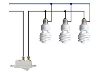
Residential electrical installations diagram three spotlights in parallel
In this installation the spotlights are connected in parallel, being able to control them through a switch the lights are connected of two lines, different to the connection in series, in which the same line all are connected, closing the last focus The circuit. This type of connection is known as a parallel circuit and is the one commonly used in all residential electrical installations.Diagram 4.
Residential electrical installations mixed circuit diagram
Spotlights are controlled in the same way by a simple damper; it is a mixed circuit (series and parallel) in which the connection can be clearly observed in any of the forms, as shown in the diagram. This way of connecting is also impractical and has strong voltage drops in the bulbs in series.Diagram 5.
Residential electrical installations damper and contact
In the following diagram we show you how a damper and a contact are connected, either in the boat or in the connection box.Diagram 6.
Residential electric installations independent lights
In this diagram we show you how to connect lights in parallel, controlled for two switches in independent circuits.Diagram 7.
Residential electric installations three-way switches in common bridges
The diagram shows the connection of a focus controlled by two three-way switches, also known as "ladder"; to do so, it is recommended to use colored cables so there is no confusion. Although it seems otherwise, this installation is very simple, which can be seen in the following figures. This method is known as "common bridges".Diagram 8.
Residential electrical installations three way short circuit switches
Another way to connect the three-way switches, known as "short circuit" installation. Although this form is widely used, it is not recommended because it results in a dangerous installation, in which despite being off the focus, the two cables that feed it can be energized, causing risk of electric shock for anyone try to change the focus.Diagram 9.


No comments:
Post a Comment