A residential electrical circuit has many parts for a correct operation but among them stand out, a voltage source, a switch for the control of the current, the conductors and a receiver or consumer, for this specific case would be our rosette and the lamp.
In our parallel circuit we observe, a voltage source, conductors, a switch and three lamps, this is the third connection that is studied in residential electrical installations. And it is very common to see or use them.
In schools are often used prefabricated boards with octagonal boxes, hexagonal or four sides, this with the intention of simulating a residential electrical installation, for this article we will depart from that option and use prefabricated boards as the image below. In which we observe, the service mufa, the load center, the metallic type pipe to make our wiring and the boxes where the components of our installation will go.
Connection and Installation of a Parallel Circuit
Installation instructions for our circuit:
- Service and load center, located on the left hand side of the board, where we organize electrical energy inputs and outputs.
- Live Line (L1) and Neutral Line or return line (Ln), which leave and enter the load center.
- A simple switch (Is1 or S1) located in the first box, to which the live line first arrives, to the switches only the live line can arrive, since it is necessary to remember that this device serves to control the passage of the electricity through the circuit.
- After we have a rise to the Lamp Lp1, Lp2 and Lp3 this rise is made with the live line that comes from the simple switch, of these lamps respectively a neutral line which we connect to the main neutral line and take to the center of load that connects with the service mufa.
- Note that the switch can go in any box below, but for order effect we have placed it in the first one, in a real installation, we will put the switch in the most accessible point for its correct use.
Applied theory:
One of the main characteristics of a parallel circuit is the way its receivers; that for this case are our three lamps, they will consume the electric current in a uniform or equitable way, since if we observe the electric circuit finished we will see that the lamp one, shines with the same intensity as lamp two and lamp three.Then we can say that the electric power is divided into equal parts, and this is due to the joints made in the main line (neutral and live) that give rise to the lamp. The voltage and amperage shown in each lamp will be equal between them.
Connection of components:
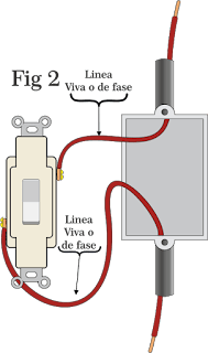
Fig2: Note that the switch is only powered by the live or phase line since this device has the sole function of controlling the passage of electrical current.
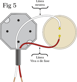
Fig5: To the rosette of the lamp arrive two lines, one is the derivation made of the live line that leaves the switch and the other is the neutral line that goes down from the lamp to make its respective connection in the neutral or common line of the circuit .
Fig6: Observe that we have left the switch on the bottom to show how the line that leaves this device is connected by making derivations or "T" junctions, so that the electric current can be divided equally by all the rosettes.


No comments:
Post a Comment