RLC parallel circuit analysis
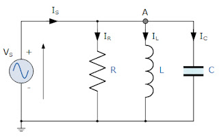
This time, instead of the current being common to the circuit components, the applied voltage is now common to all we need to find the currents of the individual branches through each element. The total impedance, Z of a parallel RLC circuit is calculated using the circuit current similar to that of a parallel circuit DC, the difference this time is that the admission is used in place of the impedance. Consider the RLC circuit in parallel below.Parallel Circuit RLC
In the previous RLC parallel circuit, we can see that the supply voltage, V S is common to all three components, while the supply current I S consists of three parts. The current flowing through the resistor, I R, the current flows through the inductor, I L and the current through the capacitor, I C.
But the current that flows through each branch and therefore each component will be different from each other and to the supply current, I S. The total current absorbed from the network will not be the arithmetic sum of the three currents of the individual branches, but its vector sum.
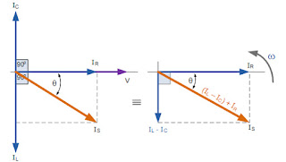
Like the RLC series circuit, we can solve this circuit using the phasor or vector method but this time the vector diagram to have the voltage as reference with the three current vectors represent with respect to the voltage. The phasor diagram for a parallel RLC circuit is produced by combining together the three individual phasors for each component and the addition of vector vector currents.
Since the voltage across the circuit is common to all three circuit elements we can use this as the reference vector with the three current vectors in relation to this drawn at their corresponding angles. The resulting vector I S is obtained by adding two of the vectors, I L and I C, and then adding this sum to the remaining vector I r. The resulting angle obtained between V and I S will be the circuit phase angle as shown below.
Phasor diagram for an RLC parallel circuit
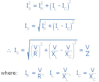
We can see in the phasor diagram on the right hand side above that the current vectors produce a right triangle, forming part of the hypotenuse IS, horizontal axis that R and vertical axis IL - I ç We hope you can notice then , that this forms a Current triangle therefore, and we can use the Pythagorean theorem in this current triangle to mathematically obtain the magnitude of the branch currents along the x axis and the y axis and then determine the total current IS of these components as shown.
Triangle current for a parallel RLC circuit
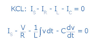
Since the voltage across the circuit is common to all three circuit elements, the current through each branch can be found using Kirchoff's current law, (KCL). Kirchoff law or law current union states that "Introduction of the total current of a junction or node is exactly equal to the current leaving the node", so the currents entering and leaving the previous node "A" is given as :
Taking the derivative, dividing through the above equation by C and rearranging gives us the following second order equation for the circuit current. It becomes a second-order equation, because there are two reactive elements in the circuit, the inductor and the capacitor.
The opposition to current flow in this type of AC circuit is composed of three components: X L X C and R and the combination of these three gives the circuit impedance, Z. We know from above that the voltage has the same amplitude and phase in all the components of an RLC circuit in parallel. Next, the impedance across each component can also be described mathematically according to the current flowing through, and the voltage across each element as.
Impedance of an RLC parallel circuit
You will notice that the final equation for an RLC parallel circuit produces impedance complexes for each parallel branch, since each element becomes the reciprocal value of the impedance, (1 / Z) with the inverse of the impedance being called admission.
In circuits of alternating current in parallel is more convenient to use the admission, symbol (Y) to solve the complex especially when they are involved two or more parallel branches of impedance (help with the mathematics of) the impedance of the branch. The total admittance of the circuit can simply be found by adding the admittances in parallel. Next, the total impedance, Z T of the circuit will be, therefore 1 / Y T Siemens as shown.


No comments:
Post a Comment