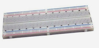
What are the protoboard?
What Are They and How to Use a Protoboard
In a simple way, it is a kind of plastic board with holes electrically connected to each other, so you can insert electronic components and cables to assemble circuits without the need to weld the components. The breadboard or protoboard that we use today was invented in 1971 by Ronald J Portugal of EI Instruments (Dato Geek).
The Protoboard serves us to experiment with electronic circuits, ensuring the smooth operation without the danger of losing components. Basically it allows us to play and create different projects without the need to lose the pieces (I will show you later how to make your circuit boards and all that ... but I'm still not very good at teaching them).
Using a BreadBoards / Protoboard
NOTE: The protoboard is not designed for high-intensity connections or high-voltage circuits.There are various types of breadboard in the market, large, medium, small, some have nodes for external power, others incorporate directly into a power source but the main thing is that they share a very similar structure.
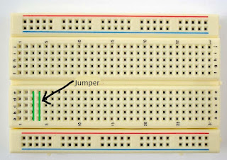
The normal thing is that the protoboars are marked with numbers and letters to facilitate the maximum placement of each component. These indications are not absolutely necessary, they are only a guide model but they are very useful with the most complex circuits.
It is interesting to say that the vast majority of models have side tabs that allow you to join several protoboards to form a much larger work surface, in addition to this and some protoboars have an adhesive sheet on the bottom which stick them to almost any surface .
Inside the protoboards we find several pieces of metal (copper, tin, nickel) that connect the outer holes to each other in certain ways.
Building a Circuit on Breadboard for Beginners in Electronics
The nodes have connections between them, so they conduct electricity along the breadboard, although some manufacturers divide that length into two parts in order to be able to different voltages on the same plate.The tracks provide points of contact for the pins or terminals of the electronic components that you will use in the breadboard, obviously following the scheme of your circuit. The tracks lead the pulses as they present in the drawing. Each track has no physical connection between them, if you want you have to use cables and connect jumpers.
To connect the components we just have to click on the breadboard respecting clearly the diagram of tracks and nodes, if it is necessary to use jumper cables, you have to choose a suitable cable such as the rigid cable of 22AWG or telephone, if we use a thicker cable , we could permanently deform the clamps inside, causing the contacts to stop being reliable.
We must emphasize that a misuse of connections or use of inappropriate voltages can spoil the protoboads and what is worse, you could lose the components you are using, so do not get creative, you always have to work with responsibility and intelligence .
In conclusion, if we want to mount a simple circuit in the breadboard, there are many ways to do it and these are practically endless. The way you interconnect each component will depend practically on how ordered you are and how visionary you are.
We already know about resistors, LEDs, capacitors and protoboards, I will talk about the next transistor post and the basic integrated circuits (NE555, NE556, 4016, 40102) and then we will start to build small projects. I know I have not talked about all the components, there are many more, but I will explain them as we use them.


No comments:
Post a Comment